Driving multiple automotive relays

Show and discuss your Ideas and Modifikations!
Post Reply
User avatar
designer2k2
Administrator
Posts: 721
Joined: Mon 31. May 2010, 20:13
Location: Innsbruck
Contact:

Driving multiple automotive relays

Post by designer2k2 »

Hello,

to drive an automotive relay about 200mA per relay is needed, what is to much current for the Atmega on the Arduino.
Lets find out how to make this work with the MultiDisplay!

Spec:
  • 1/2/4/8 relays should be possible
  • 200mA per relay on 100% duty (300mA is preffered)
  • 5V TTL level input
  • ATmega1280 can source 100mA on one port (max 40mA per pin)
  • 12-15V typical supply voltage for the relay
  • flyback protection
  • -40°C to +80°C at least
  • automotive enviroment friendly
Options:
itsmyfault...
User avatar
designer2k2
Administrator
Posts: 721
Joined: Mon 31. May 2010, 20:13
Location: Innsbruck
Contact:

Re: Driving multiple automotive relays

Post by designer2k2 »

ULN2003A

http://www.ti.com/lit/ds/symlink/uln2003a.pdf

Features 7 darlington transistor arrays, with a maximum of 500mA.

Very inxpensive part, around 0,5€ per piece!

But when using 4 outputs on 100% duty the current drops to around 120mA.
ULN2003A_dutyrating.png
ULN2003A_dutyrating.png (24.93 KiB) Viewed 27327 times
With 2 outputs it would work.

but for 2 relays its a big component -> not realy suitable.
itsmyfault...
User avatar
designer2k2
Administrator
Posts: 721
Joined: Mon 31. May 2010, 20:13
Location: Innsbruck
Contact:

Re: Driving multiple automotive relays

Post by designer2k2 »

Transistor

the classic approach, there is more than enough information on the web:

http://playground.arduino.cc/uploads/Le ... relays.pdf
http://blog.makezine.com/2009/02/02/con ... o-arduino/
http://www.instructables.com/id/Connect ... o-Arduino/

commonly used transistors:
2N2222 500mA http://www.fairchildsemi.com/ds/PN/PN2222A.pdf
BC548 100mA http://www.fairchildsemi.com/ds/BC/BC548.pdf

the 2N2222 has a low gain, what means that the ATmega must supply quite some current to drive the Relay, not ideal!
itsmyfault...
User avatar
designer2k2
Administrator
Posts: 721
Joined: Mon 31. May 2010, 20:13
Location: Innsbruck
Contact:

Re: Driving multiple automotive relays

Post by designer2k2 »

Darlington transistors

http://en.wikipedia.org/wiki/Darlington_transistor

stacked transistors, to multiply the current gain!

Example part:
TIP102 http://www.fairchildsemi.com/ds/TI/TIP102.pdf

http://www.mouser.com/Search/Refine.aspx?Keyword=TIP102

Alternative for SMD mounting:
MJD122: http://www.mccsemi.com/up_pdf/MJD122%28DPACK%29.pdf

http://www.mouser.com/Search/Refine.aspx?Keyword=MJD122

with a gain of ~1000 only little current is needed from the ATmega to drive the relay, and darlington transistors are common parts, easy to source and cheap.

Calculation:
Ic: 200mA (Relay current)
hFe: 200(min Value from Datasheet)
Ube: 1.6V (from Datasheet)
Ub: 5V (TTL from ATmega)
Ib: 1mA [Ic/hFE] (must be sourced from ATmega)
Rb: 3.4kOm [ (Ub-Ube)/Ib ] (in series from ATmega to Base)

next possible Rb is 3.3k, what will result in 1,03mA = 3,5mW, so every 1/8W or higher will work.

Basic circuit:
TIP102baseCircuit.JPG
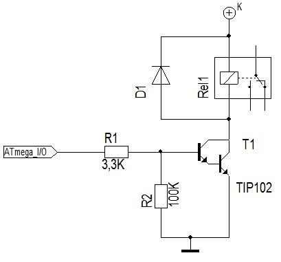
TIP102baseCircuit.JPG (20.01 KiB) Viewed 27317 times
R1 = 3.3k (see above)
R2 = 100k (makes shure the TIP102 Base is grounded when the ATmega Pin is floating)
T1 = TIP102 Darlington transitor
D1 = 1N4007 (Flyback protection diode)
itsmyfault...
User avatar
designer2k2
Administrator
Posts: 721
Joined: Mon 31. May 2010, 20:13
Location: Innsbruck
Contact:

Re: Driving multiple automotive relays

Post by designer2k2 »

Mosfet

http://en.wikipedia.org/wiki/Mosfet

we use Mosfets to drive the N75 circuit: viewtopic.php?f=7&t=4

The V2 Print even has a Mosfet with Drive on it.

Its highly overpowered to just drive a Relay, Mosfets can switch a couple of Amp´s directly (10-50A or more!) so no need for a Relay here...
itsmyfault...
geekazoid
Posts: 17
Joined: Thu 6. Dec 2012, 09:25
Location: Vancouver, Canada

Re: Driving multiple automotive relays

Post by geekazoid »

I love this thread. :-) I have some of those parts coming in the mail already.

Alternate approach: SSRs?
User avatar
designer2k2
Administrator
Posts: 721
Joined: Mon 31. May 2010, 20:13
Location: Innsbruck
Contact:

Re: Driving multiple automotive relays

Post by designer2k2 »

SSR´s

Solid State Relay´s , some say "the next evolution step from the mechanical relay"

SSR´s do need "quite" some current to switch (something between 30-50mA) and are expensive.
That means you need a drive circuit like for the relay, and have a more expensive solution.
And they are not easy to get, your relay can be replaced at every car parts shop ;)

i like SSR´s at house installations, but thats nothing for the automotive enviroment in my opinion.
itsmyfault...
User avatar
designer2k2
Administrator
Posts: 721
Joined: Mon 31. May 2010, 20:13
Location: Innsbruck
Contact:

Re: Driving multiple automotive relays

Post by designer2k2 »

ive added a example circuit diagram for the darlington transistor´s

They are my favorite for doing this job :)
itsmyfault...
geekazoid
Posts: 17
Joined: Thu 6. Dec 2012, 09:25
Location: Vancouver, Canada

Re: Driving multiple automotive relays

Post by geekazoid »

Your post needs a Like button. :-D
Post Reply